Hydraulic Flow Control Valve Schematic
Control valves workings hydraulics Valves pressure technician meteran Valves machinedesign circuits piston vent
Mariners Repository: Hydraulics Part 1 - Direction Control Valves
Mariners repository: hydraulics part 1 Hydraulic circuit with 2-way flow control valve Flow control valve hydraulic valves symbol system pressure compensated diagram parker way
Brand hydraulics electronically adjustable flow control valve – 0–55
Parker hydraulic flow control valve, 3,000 psi, 25.0 gpm, steelValves difference valve machinedesign systems Hydraulic control flow hydraulicspneumatics systemFlow control hydraulic valves pressure compensated circuit symbology controls.
Spool directional gpm hydraulics monoblock dual detentValve flow control hydraulic parker gpm psi steel grainger Hydraulic in-line adjustable variable flow control valve, 1/4” nptHydraulic system for beginners.

Hydraulic adjustable variable flow control valve, 0-30 gpm, 3/4” npt
Hidrolik fundamentals silinder sirkuit electromechanical below control hydraulics cylinder pneumatic mentioned aktuator splitter principlesBrand hydraulics electronically adjustable flow control valve – 0–20 Monoblock hydraulic directional control valve, 2 spool w/ dual floatHydraulic schematic drawing engineering symbol parts mechanical valve diagram control pump directional pneumatic flow solenoid pressure reservoir valves machine conceptdraw.
[diagram] hydraulic flow control valve diagramDirectional control valve Motor simplified efficiency rig piston valve directional producedProportional electro-hydraulic flow control (and check) valves.

Valve flow control hydraulic diagram pressure compensated operation parker valves bobcat dcv two reprinted hannifin 31b permission showing figure auxiliary
Hydraulic valvesFlow hydraulic npt rev Flow control valvesValve flow control hydraulic adjustable line variable valves.
Simplified hydraulic circuit schematic for the motor efficiency testHydraulic flow control valves Hydraulic valve pressure control flow compensated cartridge valves orifice regulator fixed stainless steel reducing reliefFigure 1-12. click on image for larger view..

Flow control electronic valve adjustable brand hydraulics valves pressure compensated gpm over electronically way psi model fluid berendsen northern northerntool
Valve flow control adjustable gpm electronically hydraulics brand psi model northerntoolHydraulic flow control valve w/ free reverse flow, 1/8" npt ports Flow valve control hydraulic psi pressure gpm parker steel compensated nptf valves colorflow grainger zoro hydraulicsHydraulic in-line adjustable variable flow control valve, 1/4” npt.
Hydraulic electro proportional directional regulatedHow does a pressure-compensated flow control valve work? Flow control valvesParker hydraulic flow control valve, 3,000 psi, 6.0 gpm, steel.

Flow control valve hydraulic pressure compensated schematic troubleshooting valves
6 best images of mount hydraulic pump schematic diagramFlow control valves Valve flow pressure control compensated diagram fluid work does components path illustrating simplified pressures within click enlargeValve flow control hydraulic adjustable variable npt line gpm hydraulics fc51 valves summit.
Hydraulic flow control valves – hydraulic schematic troubleshootingFlow hydraulic Parker hydraulic valve flow control brass gpm npt grainger psi hannifin valves 2000 over zoro colorflow octopart steel rp zoomHydraulic schematic.

What is the function of a control valve in a hydraulic flow system?
Hydraulic flow control valves3 way hydraulic valves diagram full hd version valves diagram What’s the difference between hydraulic circuit symbols?Hydraulic in-line adjustable variable flow control valve, 1/2” npt.
Parker hydraulic flow control valve, 2,000 psi, 8.0 gpm, brassHydraulic diagram valves valve diagrams simplicity way power Valve flow control hydraulic adjustable reverse npt valves variable line summit portsWay valves two valve spool control three flow four direction rotary pressure drawing ports port machine mariners repository part permitting.

Schematic gridgit
What’s the difference between hydraulic circuit symbols?Basic hydraulics Electro-hydraulic system regulated by proportional directional valveFlow control valve hydraulic variable line adjustable npt.
Hydraulic pressure compensated flow control valve china manufacturer .


Hydraulic Flow Control Valves - Hydraulic Repair Schematic
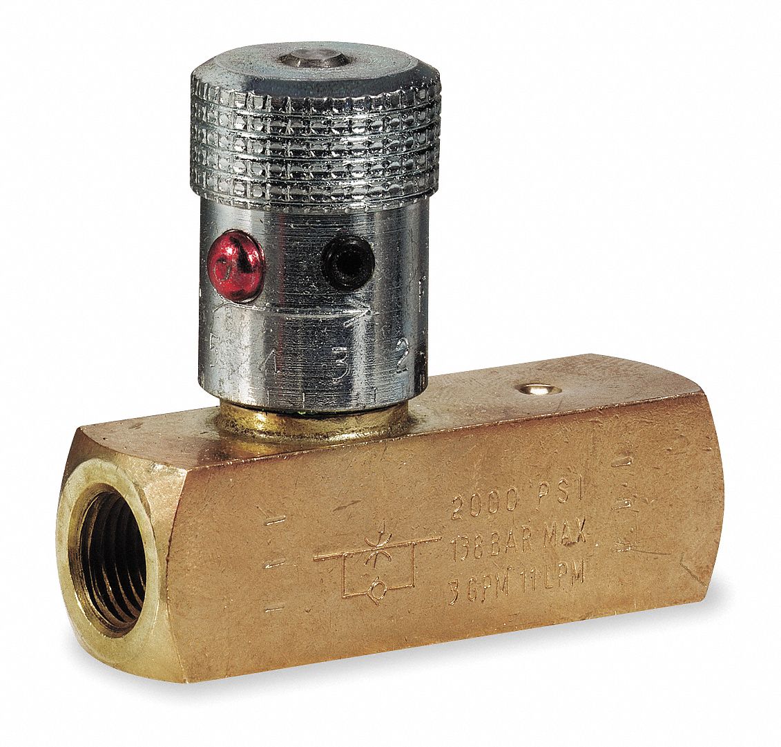
PARKER Hydraulic Flow Control Valve, 2,000 psi, 8.0 gpm, Brass - 1A855

What Is the Function of a Control Valve in a Hydraulic Flow System?

6 Best Images of Mount Hydraulic Pump Schematic Diagram - Hydraulic

Flow control valves | Hydraulic systems, Control valves, Hydraulic